 Co., Ltd.")
Laser cladding Ta-W alloy structure and high-temperature aerodynamic ablation performance
Release time:
2025-08-06
With the development of my country's aerospace technology, the requirements for parts quality and performance are also increasing. Some aerospace parts often serve in an environment with strong erosion caused by high-temperature and high-speed airflow, and are subjected to very severe aerodynamic heating [1]. This requires that the part materials must have excellent ablation resistance while meeting the processing requirements. Ordinary materials can no longer meet the ablation resistance requirements of parts in the aerospace field [2]. Materials with excellent high-temperature performance often have poor plastic processing capabilities and cannot meet the actual needs of parts. Ta-W alloy is a high-density, high-melting-point, corrosion-resistant refractory alloy material with outstanding high-temperature comprehensive performance. It has high application value in the aerospace field and is receiving increasing attention abroad [3-5]. There are relatively few studies on Ta-W alloys in China. The Northwest Institute of Nonferrous Metals has conducted a systematic study on Ta-W alloys with different W contents and obtained Ta-W alloys with excellent mechanical properties [6]. Relevant units have studied the mechanical properties of Ta-10W alloys at high temperatures [7]. However, Ta-W alloys with high W content have high strength and hardness, making them difficult to manufacture for complex parts. Laser cladding is an advanced surface coating technology. The cladding material melts under the action of laser and fuses with the substrate surface to form a metallurgical bonded cladding layer, which can improve the performance of parts or locally impart properties that the substrate does not have [8]. Laser cladding provides a feasible way to resolve the contradiction between the high-temperature service performance and processing performance of parts. Laser cladding research on high-temperature metals or alloys has been carried out at home and abroad [9-11]. Due to the extremely high melting point, easy oxidation at high temperature, and uncontrollable powder particle size of refractory metals, there are some difficulties in processing them using laser cladding methods. There are relatively few studies on this, and no relevant reports have been found on laser cladding Ta-W alloy coatings. To ensure excellent ablation resistance while maintaining good plastic processing properties, this experiment employed a coaxial powder feeding laser cladding method. Pure W powder was used as the cladding material, and Ta, a refractory metal with excellent plasticity, was used as the substrate. A Ta-W alloy coating was deposited on the Ta substrate. The microstructure, hardness, and ablation performance of the coating under high-temperature, high-velocity airflow were investigated.
1 Experiment
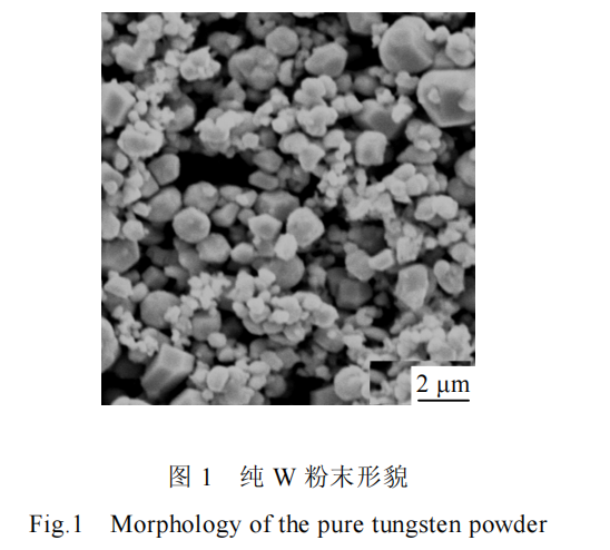
For subsequent ablation wind tunnel testing, a pure Ta plate measuring 40 mm × 30 mm was used as the substrate. The Ta plate had a trapezoidal profile with a 2 mm upper surface width and a 4 mm lower surface width. The upper surface served as the cladding surface. Prior to use, the substrate was polished and cleaned with acetone and anhydrous ethanol. The cladding material was pure W powder, and the powder morphology is shown in Figure 1. Figure 1 shows that the average powder particle size is less than 2 μm and the shape is irregular. To ensure smooth powder delivery, the powder was screened before use and dried at 90°C for 6 hours.
The laser cladding experiment used an Nd:YAG solid-state laser with coaxial powder feeding, depositing the cladding layer layer by layer. The specific processing parameters were a laser power of 1000 W, a defocus distance of 20 mm, a scanning speed of 2 mm/s, and a powder feed rate of 1 g/min. Because refractory metals are susceptible to oxidation at high temperatures, the entire process was performed in an inert gas atmosphere chamber filled with argon. Argon was also used as the powder feed gas and lens shielding gas in the experiment.
The microstructure and composition of the cladding layer were analyzed using a ZEISS EVO18 Special Edition scanning electron microscope (SEM) and a BRUKER Nano XFlash Detector 5010 energy dispersive spectrometer (EDS). The microhardness of the cladding layer was measured using an HXD-1000B electron microhardness tester with a load of 0.98 N and a hold time of 15 s. Ablation tests were conducted on the specimens in an in-line free jet wind tunnel test rig.
2 Results and Discussion
2.1 Composition and Microstructure of the Laser Cladding Layer
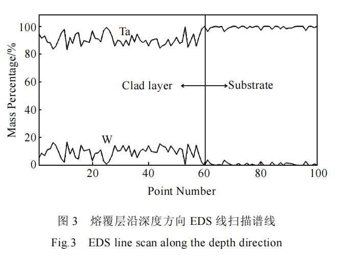
The macroscopic morphology of the cross-section of the cladding layer after laser cladding is shown in Figure 2. As can be seen, it consists of three main regions: the cladding layer, the heat-affected zone, and the substrate. The maximum thickness of the cladding layer is approximately 1.1 mm at the center, and approximately 0.5 mm above the substrate surface. The maximum width of the cladding layer is approximately 2.1 mm at the top, and the width of the molten pool gradually narrows toward the bottom. During coaxial powder feeding laser cladding, W powder particles, the cladding material, enter the laser beam as they fall, absorbing laser energy and melting. The remaining laser energy directly impinges on the Ta substrate, melting the substrate surface and forming a molten pool. The melted powder droplets, along with some larger, partially melted particles, then enter the substrate molten pool and mix with the melt. During this mixing process, the partially melted powder particles absorb the molten pool's heat and further melt, ultimately forming a molten pool containing Ta and W elements on the substrate surface. The molten pool rapidly solidifies nonequilibrium, relying on heat conduction from the substrate and radiation to the surrounding air, to form the cladding layer. In the initial stages of laser cladding, the substrate temperature is low and has not yet reached thermal equilibrium, absorbing heat. The molten pool is relatively low and small in size. As the cladding process progresses, the distance between the molten pool and the substrate increases, and the temperature gradually rises, resulting in a corresponding increase in molten pool size in the later stages of cladding. An EDS line scan of the cladding layer's center along the depth direction from point A to point B is shown in Figure 3, with the cladding layer on the left and the substrate on the right. The analysis results show that throughout the cladding layer, the mass fraction of W is roughly distributed between 5% and 15%, with the remainder being Ta. This indicates that laser cladding allows for sufficient diffusion between the cladding material and the substrate, forming a Ta-W alloy coating on the substrate surface after solidification.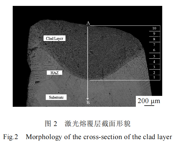
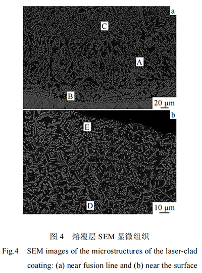
The microstructure of the cladding layer is shown in Figure 4. Figure 4a shows the microstructure near the fusion line of the cladding layer, and Figure 4b shows the microstructure near the top of the cladding layer. The microstructure after laser cladding solidification is primarily determined by the temperature gradient and solidification rate within the molten pool. The temperature gradient gradually decreases from the bottom to the surface of the molten pool, while the solidification rate gradually increases. In the initial stages of laser cladding, the laser irradiation time is short, the substrate temperature is low, and the ratio of the temperature gradient to the solidification rate at the bottom of the molten pool is large. The solid-liquid interface initially grows in a planar manner, preferentially forming at the interface between the molten pool and the substrate. After this planar interface destabilizes, a gray, flocculent structure grows above the fusion line, forming a strong metallurgical bond between the cladding layer and the substrate. As laser cladding progresses, the substrate continuously absorbs heat, increasing its temperature. The ratio of the temperature gradient to the solidification rate decreases, causing grains to preferentially grow toward the center of the melt pool, perpendicular to the fusion interface and against the direction of the heat flow, forming a dense dendritic structure. Due to local energy differences and composition fluctuations, some dendrites grow larger, and secondary dendrite arms appear. After reaching a certain size, dendrites are hindered by adjacent grains, preventing further growth. Simultaneously, under the reciprocating action of the laser beam, the already formed cladding layer is subjected to secondary irradiation, causing the upper layer to melt again and resolidify with the newly input cladding material to form a new cladding layer. The dendritic structure near the overlap of the cladding layers undergoes remelting, altering its growth direction and morphology, resulting in a sparse, short, and thick dendritic structure, as shown in the middle region of Figure 4a. As the number of cladding layers increases, the distance between the molten pool and the substrate increases, further reducing the ratio of the temperature gradient to the solidification rate. Furthermore, under the action of the moving laser beam, the liquid in the molten pool experiences intense convection, causing dendritic growth to gradually lose its directionality. After solidification, the resulting structure in the upper middle portion of the cladding layer is dense and relatively chaotic, as shown in Figure 4b. EDS point analysis of the Ta-W solid solution phase composition at different locations is shown in Figures 4a and 4b. Point A represents the black region between dendrites, while points B, C, D, and E represent dendrites at different locations. The analysis results are shown in Table 1. The W-Ta binary phase diagram shows that W and Ta are completely miscible in both the liquid and solid states, forming a continuous solid solution. EDS analysis reveals that the W content in the black region between dendrites within the cladding layer is less than 1%, indicating that the dendritic structure within the cladding layer is a Ta-W solid solution, which is roughly evenly distributed within the Ta.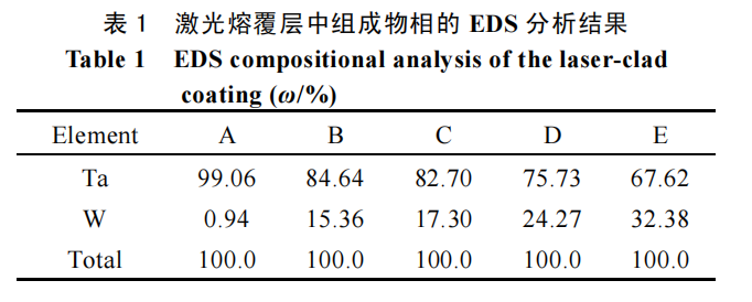
The total number of laser cladding layers in the experiment was 10. Based on the total thickness of the cladding layers and the internal microstructure variations, each layer is approximately 100 μm high. As shown in Figure 2, EDS regional analysis was performed on cladding layers 1–10. Layer 1 is located near the bottom of the cladding layer. The thickness of each cladding layer is based on the actual internal dendritic microstructure variations. The average W mass fraction of each layer is shown in Figure 5. The EDS layer-by-layer analysis results show that the W mass fraction is slightly lower near the bottom of the cladding layer in the initial stage. After reaching a stable level, the W content is relatively uniformly distributed within the range of 10%–11%. As the cladding layer height increases, the W content increases, from 6.17% to 11.04%. This compositional change in the cladding layer is due to changes in the phase composition of the Ta-W solid solution within the cladding layer. Comparing the composition of dendrites at different locations reveals that the W content of the Ta-W solid solution near the bottom of the cladding layer is relatively low, at approximately 15%. This is because, in the initial stages of laser cladding, the base melt pool is entirely Ta, resulting in a significant disparity in the Ta/W ratio. As the cladding process progresses, the cladding material is continuously transported into the melt pool, accumulating W, and the Ta/W ratio within the melt pool changes accordingly. With increasing cladding layer height, the W content gradually increases, reaching 30% near the top of the cladding layer, thus forming a Ta-W alloy coating with a compositional gradient.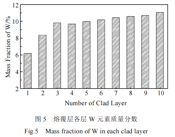 2.2 Cladding Layer Hardness
Figure 6 shows the microhardness curve from the cladding layer surface to the depth of the base layer. It can be seen that the hardness decreases from the cladding layer surface to the base layer, with varying microhardness across different regions. The cladding layer exhibits the highest hardness, but with significant heterogeneity, with an average hardness of 8 GPa and local hardness reaching as high as 11 GPa. The hardness near the fusion line of the cladding layer is slightly lower, averaging 6 GPa. The hardness in the heat-affected zone (HAZ) decreases gradually, transitioning to the substrate, where the average hardness is 1.5 GPa. This indicates that the cladding zone, rich in dense, dendritic Ta-W alloy solid solution, significantly increases the hardness of the coating, approximately five times that of the pure Ta substrate. In contrast, the area near the fusion line exhibits inadequate microstructure development during the initial stages of laser cladding, primarily consisting of flocculent or short rod-like structures, resulting in a slight decrease in hardness. The Ta in the HAZ undergoes grain refinement under the action of the high-energy laser beam, increasing its hardness. In summary, the laser-clad Ta-W alloy coating exhibits significantly higher strength than pure Ta.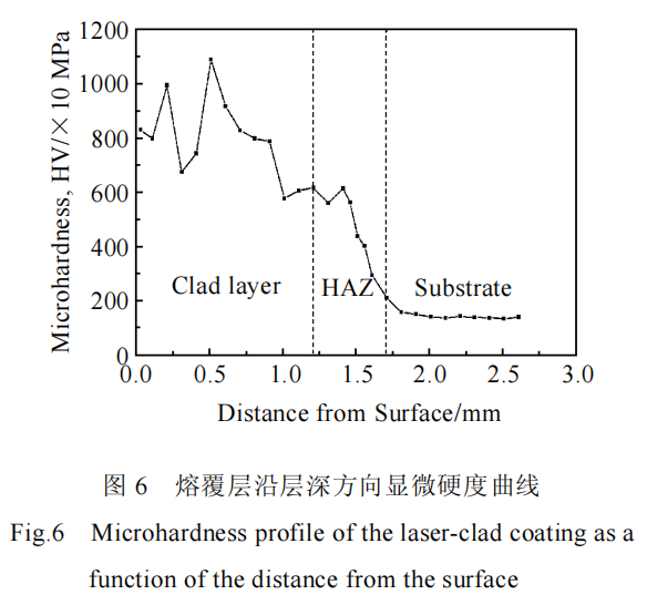
2.3 Ablation Performance of Ta-W Cladding
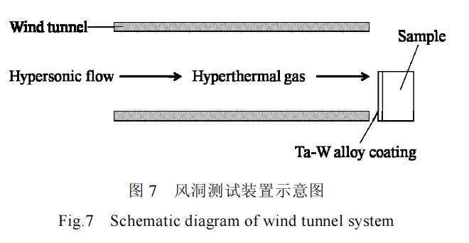
A direct-connected free-jet wind tunnel test rig was used to conduct high-temperature, high-speed airflow ablation tests on pure Ta plates and Ta plates laser-clad with a Ta-W alloy coating under identical ablation conditions. The test setup is shown in Figure 7. The test specimen was positioned at the tunnel exit, with its side perpendicular to the airflow direction to maximize the airflow impact. The high-speed airflow enters the tunnel at the inlet and mixes thoroughly with kerosene. The mixed oil and gas are ignited in the combustion chamber. The resulting high-temperature airflow is then blown out of the tunnel outlet, forming an extremely high-temperature, high-speed airflow at the outlet that erodes the specimen. Specific test environment parameters are shown in Table 2.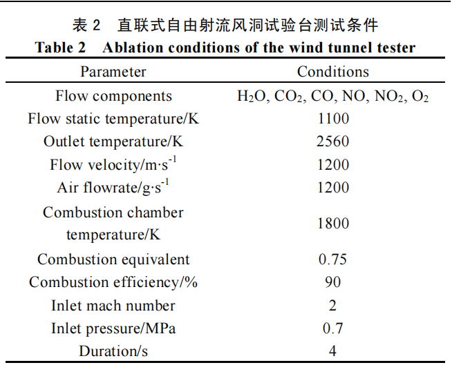
The ablation test results are shown in Figure 8. Figures 8a1 and 8a2 show the macroscopic morphologies of the pure Ta specimen before and after ablation, while Figures 8b1 and 8b2 show the macroscopic morphologies of the specimen with a Ta-W alloy coating laser-clad at the front end before and after ablation. As shown in the figure, the front end of the pure Ta metal plate shows significant damage after 4 seconds of ablation, with the most severe damage occurring near the tip. This is due to the shock wave generated by the high-speed airflow at the sample tip, coupled with the extremely high temperature, resulting in a very high heat flux density near the leading edge stagnation point, making it highly susceptible to ablation. Although pure Ta has a melting point of 2990°C, which is higher than the airflow temperature and prevents melting, the material surface experiences significant shear stress under supersonic high heat flux conditions. The rapid increase in temperature reduces the material's yield strength, and the impact of the high-speed airflow on the material causes plastic deformation of the sample. Furthermore, the ablation process involves chemical attack in addition to mechanical erosion. Oxygen in the airflow oxidizes the Ta at high temperatures, further exacerbating the sample's ablation damage. In contrast, the sample with a Ta-W alloy coating on the front end showed no significant deformation or damage after the same ablation time. The front edge retained its original shape, with only the triangular region where the tip resided changing color during the heating process, indicating significantly improved ablation resistance. This is primarily due to the fact that the Ta-W alloy coating laser-clad on the front end of the specimen not only possesses a high melting point but also possesses a dense internal structure, high strength, and high-temperature performance. The dendritic Ta-W solid solution reinforcement provides excellent support and adhesion to the material during ablation, hindering plastic deformation caused by the impact of the high-speed airflow. Furthermore, the Ta-W alloy exhibits superior high-temperature oxidation resistance compared to pure Ta, thus protecting the pure Ta substrate.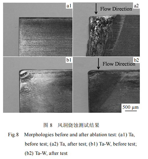 3. Conclusions
1) Using coaxial powder feeding laser cladding, pure W powder as the cladding material and pure Ta as the substrate, a Ta-W alloy coating with an average W content of 5%-15% can be deposited on the Ta plate surface, demonstrating excellent metallurgical bonding between the coating and the substrate.
2) The alloy coating contains a dense, dendritic Ta-W solid solution uniformly distributed throughout the Ta. The Ta-W solid solution increases the microhardness of the cladding layer to approximately 8 GPa, five times that of the pure Ta substrate. 3) Under the same high-temperature, high-speed airflow ablation test conditions, the pure Ta sample suffered significant burnout, while the sample with the Ta-W alloy coating showed no significant damage, demonstrating the excellent ablation resistance of the Ta-W alloy coating.
Paper Citation Information
Rare Metal Materials and Engineering, Volume 41, Issue 7
Microstructure and High-Temperature Aerodynamic Ablation Performance of Laser Cladding Ta-W Alloy
Chinese Library Classification Number: TG146.4+16;
TN249 Document Identifier:
A Article Number: 1002-185X(2012)07-1211-05
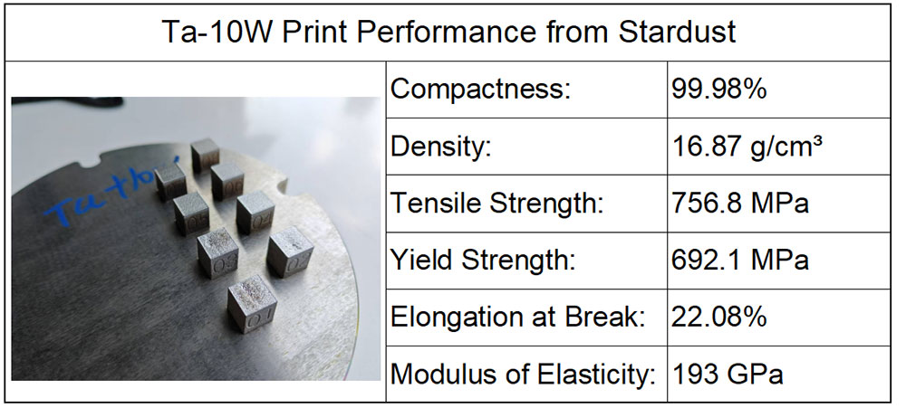
Stardust Technology's spherical Ta-10W alloy powder is produced using a radio frequency plasma spheroidization process. It features high purity, low oxygen content, high sphericity, a smooth surface, no satellites, uniform particle size distribution, excellent flowability, and high bulk and tap densities.
http://en.stardusttech.cn/products/57.html
For more refractory metal spherical powder products, please contact Vicky Zhang at +86-13318326185

News
Stardust Technology (Guangdong) Co., Ltd.

101, Building 1, Liandong Youzhi Zone, Senshuji Road, Nansha Community, Danzao Town, Nanhai District, Foshan City,Guangdong Pro.,China
Tel:13318326187
13378621675
QR code