Research on fiber laser welding of Nb521 high temperature alloy and joint organization and properties
Release time:
2025-01-08
Niobium-tungsten alloy Nb521 (Nb-5W-2Mo-1Zr) is a kind of high-temperature alloy independently developed by China, which has a high melting point, good high-temperature (1650°C) strength, and compared with refractory metals, such as tungsten, molybdenum and tantalum alloys, it has the advantages of low density and good room-temperature plasticity, and it can be processed into a wide range of complex shaped parts [1-2]. Therefore, Nb521 has been regarded as a preferred high-temperature structural material for space vehicles, supersonic airplanes, missiles, etc., and has received wide attention in aerospace and nuclear industries. This class of alloys is applied to the manufacture of thrust chambers of binary liquid rocket engines, and the engine thrust ratio and operating temperature have been substantially increased under the protection of molybdenum silicide coating, and the operating temperature of the thrust chambers is as high as about 1,550°C [3]. With the rapid development of China's aerospace technology, the potential application areas of Nb521 niobium-tungsten alloy are even broader, and its application in high-temperature components of various types of high-speed vehicles has gradually attracted attention [4]. In order to further expand the scope of application of Nb521 materials in the aerospace field and provide more space for structural design to play, it is necessary to study the welding process and joint quality of Nb521 alloy.
Nb521 alloy material itself weldability is good, but there is a problem of poor oxidation resistance. When the temperature exceeds 400 ℃ Nb521 oxidation accelerated, the formation of easy to break off in the oxidation process of Nb2O5, become the main factor restricting its application at high temperatures, but also to the Nb521 welding problems [5]. Therefore, the surface of Nb521 high-temperature components usually need to prepare protective coatings [6], and the welding method of Nb521 is also mainly focused on the electron beam welding [7-12].2021, Zhu Dongmei et al [7] carried out a study on the optimization of the electron beam welding process of the Nb521 alloy, and analyzed the joint morphology, microstructure, room temperature and high-temperature mechanical properties of the joints, and the room temperature tension of the optimized Nb521 niobium-tungsten alloy was found to be very high. The room temperature tensile strength and elongation of the optimized Nb521 niobium-tungsten alloy electron beam welded joints were able to reach 95% and 86.7% of the parent material, respectively. The test results show that the strength of the joint decreases and the elongation increases with increasing temperature. The tensile strength of the joint at 1600℃ is about 110MPa, the elongation reaches about 36%, and the tensile fracture is toughness fracture. It is worth noting that when the temperature is further increased to 1800 ℃, the elongation of the weld metal decreases rapidly to about 12%, and the tensile fracture of the weld at 1800 ℃ is brittle fracture. Zhu Mingde et al [8] used electron beam welding method to weld the weld between Nb521 alloy connecting ring and nozzle body, the weld cracking occurred in the vibration test, the analysis concluded that the crack is caused by low-melting eutectic impurities, and the pre-weld cleanup is very important for the quality of the Nb521 e-beam weld head. For the gas pedal pure niobium superconducting cavity of the welding surface morphology and performance requirements of the demanding challenges, Fang Yuchao et al [9] used experimental and CFD numerical calculations to carry out an in-depth study of electron beam scanning cross-welding of thin niobium plate molten pool kinetic behavior.
Heterogeneous welding techniques between Nb521 and other materials, which can enrich the form of structural design, have also been an issue of great interest in recent years. For example, Bai Run et al [10] investigated the weldability of Nb-Ti-Al-based low-density niobium alloy (LDNb) own welding with high-strength niobium alloys, high-temperature titanium alloys and other alloys by using vacuum electron beam welding, and found that the use of the beam bias to the side of the high-melting-point material can be obtained with well-formed welded joints, and the obtained LDNb joints, LDNb/Nb521 joints and LDNb/TC4 The room temperature tensile strength of the obtained LDNb joints, LDNb/Nb521 joints and LDNb/TC4 joints reached more than 90% of the strength of the base material, and the elongation of the joints was similar to the base material. Wang Feng et al [11] found that the room temperature tensile strength of electron beam welded heterogeneous joints of low-density niobium alloys and Nb521 alloys was similar to that of the base material, and the tensile strength of the joints decreased after post-weld heat treatment at 1000°C/1h and 850°C/1h. Zhang et al [12] performed vacuum electron beam welding of Ti3A1-based alloy with Nb521 niobium alloy, and found that there was a more obvious compositional inhomogeneity in the weld, but the joints had excellent room-temperature mechanical properties, and the room-temperature tensile fracture was on the side of the Nb521 base material, with an elongation of about 13.8%. These research advances mentioned above are of great significance for expanding the scope of application of Nb521 and broadening the space of high-temperature structural design innovation.
Fiber laser deep fusion welding technology based on and electron beam welding process similar to the “keyhole effect”, can also form a large depth to width ratio of the weld, with a small specific energy, small heat-affected zone, small deformation, the advantages of high efficiency. Zhang Lixu et al [13] organized the research progress of key technologies at home and abroad, such as all-position laser welding of ultra-high-strength steel thick-walled structures, single-pass full-penetration welding, power-modulated laser welding, and simulation of laser weld pool dynamics, and systematically demonstrated the potential application of these new advances in the quality control of laser welding of ultra-high-strength steel solid rocket motor casing. Liu Menghan et al [14] studied the laser welding of TC4 titanium alloy and 50 steel dissimilar materials, analyzed the crack extension of the joint and the microstructure of the weld as well as the composition of the physical phase, concluded that the type and location of cracks are related to the process parameters, and concluded that the main reason for cracks to sprout and expand is the high hardness of high-carbon martensite and TiFe, TiFe2 intermetallic compounds, as well as the difference in toughness and plasticity. Yingjie Wang et al [15] had studied the laser spot welding of two different thickness combinations of niobium-hafnium alloy lap joints, analyzed the relationship between welding power, weld depth of fusion and weld resistance to shear damage, and determined a reasonable laser spot welding process specification. However, there are very few studies involving laser deep fusion welding of Nb521 alloy, mainly due to two reasons: one is that the maximum plate thickness that can be welded by laser deep fusion welding for a long time is limited by the maximum power level of commercial lasers, which is obviously inferior to the electron beam welding; the second is that Nb521 itself is easy to oxidize, and the electron beam welding is carried out in a vacuum chamber, which can effectively avoid this problem.
In recent years, high-power fiber laser technology has become increasingly mature. Considering that compared with electron beam welding, fiber laser deep melting welding has many advantages such as no restriction of vacuum chamber, no need of vacuum extraction process, no X-ray problem, no need of demagnetization treatment of workpiece, etc., it is necessary to carry out the weldability of fiber laser deep melting welding of Nb521 alloy, to lay a foundation for the application of the flexible and efficient laser welding technology to the structural design and manufacture of Nb521, and to provide a A new way to solve the problem of Nb521 welding. To this end, this paper investigates the welding characteristics of 6kW fiber laser on 4.6mm thick Nb521 and the effect of different welding process parameters on the formation of welded joints, to obtain the optimized welding process parameters, organization and performance analysis shows that in the local argon protection, the use of fiber laser deep melting welding can be realized in the quality of the Nb521 connection.
1 test materials and methods
Selected 4.6mm thick Nb521 plate as the test material, its tensile strength of 487MPa, elongation of 36%, chemical composition as shown in Table 1.

The welding test was carried out by YSL-6000 fiber laser of Germany IPG company, the maximum output power was 6kW, the focusing distance was 195mm, the core size was 300μm, the minimum spot diameter was 200μm, and the wavelength was 1070nm. in order to ensure the quality of weld, the parts were pre-welded by pickling and mechanical grinding, to eliminate the grease and surface oxides on the weld, and the weld was finished with anhydrous ethanol, and the weld was completed by the welding process. Oxide, and anhydrous ethanol to wipe the surface clean. Using the same plate single-pass laser self-melting welding form, due to the Nb521 oxidation at high temperatures is serious, so the mass fraction of 99.999% of argon as a protective gas, to maintain the laser power of 6kW unchanged, through the optimization of the welding speed and the amount of focusing and other parameters, in order to ensure that the seam penetration under the circumstances of the case of reducing the heat input, so as to control the depth to width ratio of the weld, to avoid the weld organization is coarse, to reduce the welding stress and to Eliminate the tendency of porosity and cracks. The main welding process parameters are shown in Table 2 and Table 3.
After welding, the specimen was cut along the cross-section, polished with 400, 600, 800, 1000, 1200, 1500, 2000 mesh water sandpaper, and polished with diamond polishing paste on a polishing machine, and after polishing, chemical corrosion was carried out using chemical reagents with the volume ratio of V (HF) ∶ V (HNO3) ∶ V (H2O) = 1:1:1 (in which the mass fraction of hydrofluoric acid is greater than or equal to 40%, nitric acid mass fraction is greater than or equal to 40%, nitric acid mass fraction is greater than or equal to 40%, and nitric acid mass fraction is less than or equal to 40%. (in which the mass fraction of hydrofluoric acid is more than or equal to 40%, and the mass fraction of nitric acid is 65%~68%), and the macroscopic morphology and microstructure of the weld were observed by Nikon Eclipse MA200 optical microscope. The microhardness of the joints was measured by XHVT-1000Z intelligent microhardness tester. The tensile test was carried out on CSS-88100 tensile machine, the size of the tensile specimen was shown in Fig. 1, the tensile load loading speed was 2mm-min-1, and the average value of the test results of 3 specimens was taken. SU3500 scanning electron microscope was used for tissue observation and fracture morphology analysis.
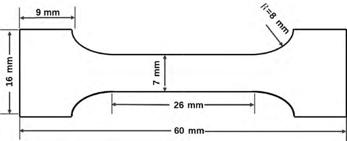
Fig. 1 Schematic diag ram of tensile specimen


2 test results and discussion
2.1 Weld surface molding and cross-section morphology
When the laser power is maintained at 6kW, the amount of focus is 0mm, argon flow rate of 35L/min, different welding speeds under the weld surface molding and weld cross-sectional morphology shown in Figure 2. As can be seen from Figure 2, when the welding speed of 2535mm/s, the weld are completely melted through, the weld are not found inside the pores, cracks and other defects; with the increase in welding speed, the stability of the molten pool is affected by the gradual deterioration of the continuity of the weld, when the welding speed reaches 55mm/s, the back of the seam appeared discontinuous hump; weld speed, can be part of the improvement in the collapse, to mitigate the edge biting defects. The effect of welding speed on melt width is shown in Figure 4(a). From Fig. 4(a), it can be seen that the weld melt width decreases with the increase of welding speed.
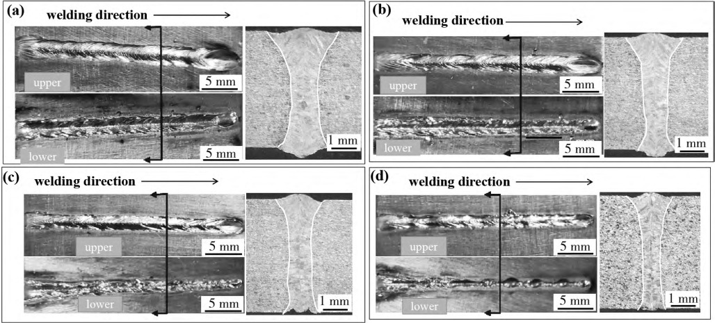
Fig.2 Weld surface and cross-sectional morpholo gy of different welding speeds (laser power : 6 000 W , defocusing : 0)
(a) Welding speed : 25 mm/s; (b) Welding speed : 35 mm/s; (c) Welding speed : 45 mm/s; (d) Welding speed : 55 mm/s
When the laser power is 20kW, the welding speed is 45mm/s, and the argon flow rate is 35L/min, the effects of different defocusing amounts on the surface shaping and cross-sectional morphology of the weld are shown in Figure 3. As can be seen from Fig. 3, when the defocusing amount varies from 0 to +2mm, the weld is uneven, discontinuous and has a hump, the spatter gradually becomes serious, and there is a serious collapse of the frontal weld accompanied by the phenomenon of biting edges, which may be caused by the recoil pressure of the metal vapor, as well as the surface tension of the molten metal and the force of gravity. The weld was not welded through when the defocusing amount reached +2mm, due to the decrease of laser energy density per unit area on the surface of the workpiece; when the defocusing amount varied from 0 to -4mm, the weld gradually became discontinuous from continuous, and a discontinuous hump appeared at -2mm, and finally no weld was welded through when the defocusing amount was -4mm. The biting edge on the lower surface was improved, and the change on the upper surface was not obvious. As can be seen in Fig. 3, the weld is formed continuously with a relatively smooth surface at -1 mm, with almost no edge biting and collapse, and the forming is better. The effect of the amount of scorch off on the melt width is shown in Fig. 4. From Fig. 4(b), it can be seen that with the change of the amount of focus from -4mm to 2mm, the upper melt width decreases and then increases, which is the smallest in the amount of focus -1mm; the middle melt width with the change of the amount of focus is not obvious, but it can be seen that in the amount of focus -1mm at the melt width is the smallest; due to the existence of the case of weld penetration, under the rule of change of melt width with the amount of focus is uncertain, the figure defaults to the case of weld penetration, the melt width of zero.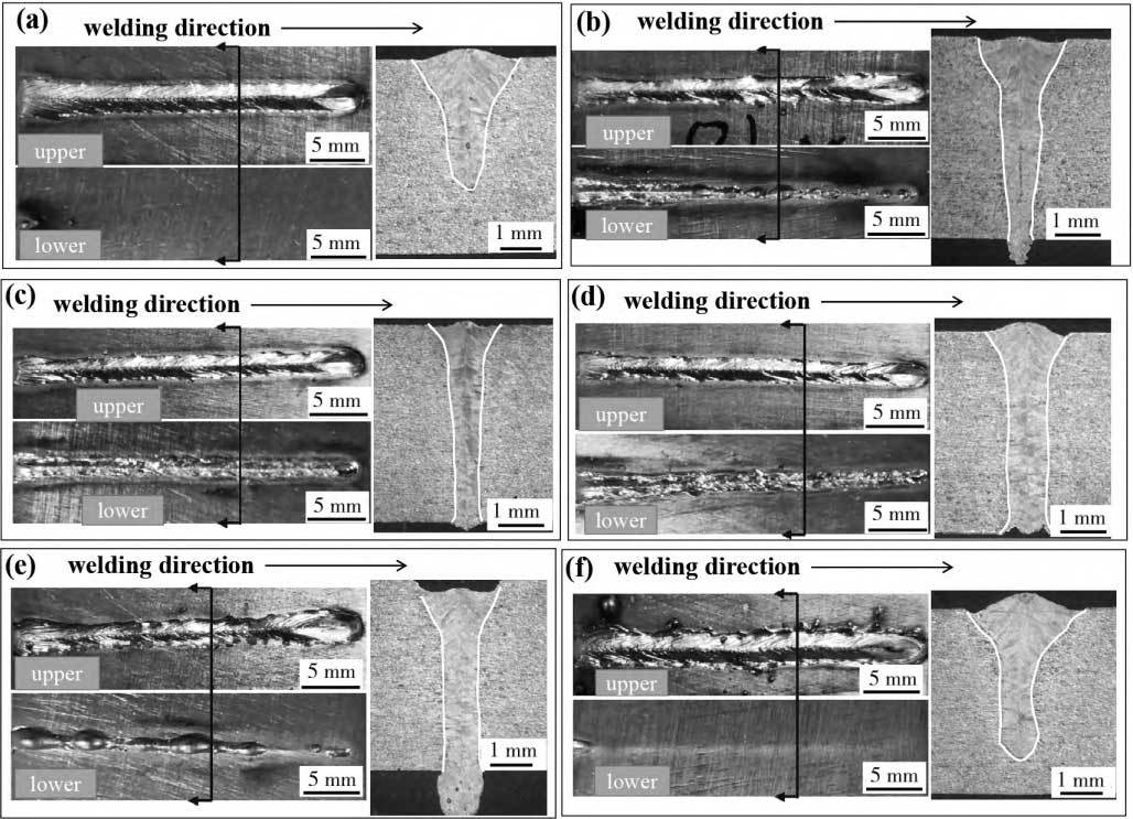 Fig.3 Surface and cross-sectional morpholo gy of welds with different defocusing (laser power : 6 000 W , welding speed : 45mm/s). welding speed : 45mm/s)
(a) Defocusing : -4mm; (b) defocusing : -2mm; (c) defocusing : -1mm; (d) defocusing : 0mm ; (e) defocusing : +1.5mm; (f) defocusing : 0mm; (g) defocusing : 0mm; (h) defocusing : 0mm.
(e) defocusing : +1mm; (f) defocusing : +2mm.
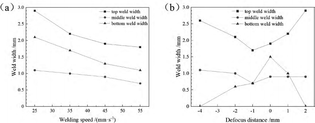
Fig. 4 The influence of p rocess parameters on weld width (a) Welding speed; (b) defocusing
2.2 Microstructure analysis
From the above analysis, the optimized process parameters are as follows: laser power of 6 kW, welding speed of 45 mm/s, defocusing amount of -1 mm. The macroscopic morphology of the welded joint and the microstructure of the weld obtained by the optimized process are shown in Fig. 5. The macroscopic morphology of the weld is shown in Fig. 5(a). The upper part of the weld is elongated columnar crystals, the grains are relatively coarse, and their direction is perpendicular to the fusion line. The columnar crystals are tightly attached to the base material and grow towards the center of the weld against the direction of heat conduction, which has the characteristics of associative crystallization and epitaxial growth. The center of the weld becomes the location where the grain orientation changes on both sides, as shown in Figure 5(b). Figure 5(c) for the weld middle microstructure, where the same characteristics of associative crystallization, the crystallization process in the melt pool boundary began, non-spontaneous nucleation dependent on the surface of the half-melted base material grains, along the half-melted base material grains to the center of the weld growth [see Figure 5(h)]. Heat flow direction perpendicular to the fusion line, in the growth process, there is a tendency to compete for growth, and the direction of the temperature gradient in line with the grain orientation of the growth rate is fast, and has been growing to the center of the weld for the elongated and thick columnar crystals; on the contrary, can only be grown to a certain size and termination, for the short and thick columnar crystals. As can be seen from Figure 5(d), the lower part of the weld is similar to the upper part, due to the direction of the heat flow, the weld center line on both sides of the grain direction perpendicular to the fusion line, while near the center line and the bottom position of the grains have a tendency to go downward, the main reason is that the weld solidification, a portion of the heat to the bottom of the dissipation. Tiny air holes are seen in the lower part of the weld, probably due to the good thermal conductivity of niobium alloy, the cooling rate is fast, and the air holes are not able to escape in time.
From Figure 5(e), 5(f), 5(g), it can be seen that the size of the heat-affected zone is small, isometric crystals, grain size relative to the base material is relatively coarse and slightly elongated along the vertical direction of the fusion line, there is no particularly clear boundary between the heat-affected zone and the base material, the reason for this phenomenon may be that the niobium alloy has a very good coefficient of thermal conductivity, weld region of the heat is quickly transferred out of the region, so the heat-affected zone of high temperature time Shorter, narrower heat-affected zone, grain growth is not obvious, and the parent material grain size is not much difference, there is no clear boundary. Parent material organization is uniform and delicate, isometric crystal organization, as shown in Figure 5(i).
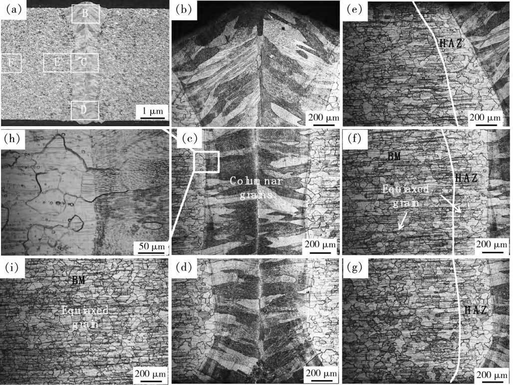
Fig. 5 Macroscopicmorp holo gy of welded joint and microstructure of weld
(a) Cross section of the weld; (b) the upper part of the weld; (c) the middle of the weld; (d) the lower part of the weld ; (e) (f) (g) the lower part of the weld; (h) the lower part of the weld; (i) the lower part of the weld
(e) (f) (g) heat affected zone; (h) enlarg ed view of fig ure (c) ; (i) base metal
2.3 Mechanical Properties Analysis
2.3.1 Tensile mechanical properties
Tensile test on the specimens after using the optimized parameters, respectively, take three welded joints tensile specimens to do tensile parallel test. Specimen 1 broken in the heat-affected zone position, the fracture occurred at the neck shrinkage phenomenon, showing toughness fracture fracture morphology, its tensile strength of 479MPa. specimen 2, 3 are broken in the position of the base material, the fracture occurred at the obvious neck shrinkage phenomenon, presenting toughness fracture morphology, shown in Figure 6. Specimen 2 microscopic morphology shows a large number of tough nests, tough nests of different sizes, and accompanied by the emergence of secondary cracks, these will absorb a large amount of energy in the fracture process, so that the tensile strength becomes good, as shown in Figure 6. The tensile strength of specimens 2 and 3 were 480 MPa and 483 MPa respectively, and their tensile strength curves are shown in Fig. 7(b). From Figure 7(a), the tensile strength of the base material was 489MPa, 484MPa, 487MPa, so whether the fracture location for the base material or heat-affected zone, the tensile strength of the weld and the base material tensile strength are comparable.
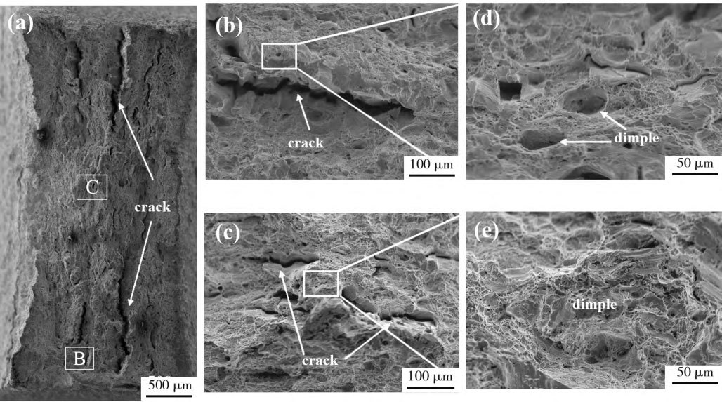
Fig. 6 Tensile fracture morpholo gy of the samp le
(a) The overall fracture morpholo gy of samp le 2; (b) enlarged view of area B in fig ure (a) ; (c) enlarged view of area B in fig .
(c)enlarg ed view of area C in fig ure (a) ; (d)enlarg ed view of fig ure (b) ; (e)enlarg ed view of fig ure (c)
Fig. 7 Load-displacement curves of tensile specimens (a) Base metal specimen ; (b) Welding specimen
2.3.2 Microhardness analysis
Hardness tests were conducted on the upper, middle and lower regions of the weld, and the hardness distribution curves are shown in Figure 8. The incomplete annealing of this specimen resulted in greater hardness on the upper and lower surfaces relative to the center. The microhardness of the upper part of the weld decreases and then increases from the base material to the weld, and the molten pool interface has very good thermal conductivity conditions and a fast cooling rate, which makes it easy to produce a hardened organization, so the hardness is very high. Heat-affected zone part of the thermal cycle due to the role of a certain degree of softening, resulting in a reduction in hardness; and in the middle of the weld, due to incomplete annealing, the hardness change presents a different situation with the upper part of the weld. From the base material zone to the heat affected zone, the hardness increases only slightly, with little difference, varying between 170 and 180 HV, while in the weld zone the hardness increases suddenly, with hardness values varying between 190 and 195 HV. In the lower part of the weld is similar to the upper part of the weld, the microhardness from the base material to the weld decreases and then increases, and the hardness value of each region is close to each other. In short, due to the laser welding larger energy density and faster welding speed, the cooling speed is faster, making the weld zone organization coarse, high hardness; due to the niobium alloy has a very good thermal conductivity, heat transfer faster, so that the organization of the heat-affected zone and micro-hardness is not much different from that of the base material.
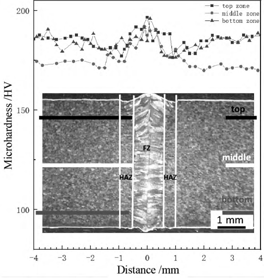
Fig. 8 Micro-hardness distribution of welded joints
3 Conclusion
Using 6kW fiber laser on Nb521 high temperature alloy welding process experimental research, studied the effect of different welding process parameters on weld shaping and macroscopic morphology, and analyzed the microstructure and mechanical properties of welded joints, and obtained the following conclusions:
(1) With the increase of welding speed, the weld melt width becomes smaller, the weld collapse is improved, but the weld continuity becomes worse.
(2) With the variation of the defocusing amount from -4mm to +2mm, the melt width becomes smaller and then increases, and it is the smallest in the vicinity of -1mm; when the defocusing amount is positive, the weld is poorly shaped, and the weld is discontinuous, and there are defects such as spatter as well as biting edges.
(3) When the laser power is 6kW, the welding speed is 45mm/s, and the defocusing amount is -1mm, the weld seam is well formed, which is the optimized process parameters.
(4) Under the optimized process parameters, the weld zone is a coarse columnar crystal organization perpendicular to the fusion line, the base material is a fine equiaxial crystal organization, and the heat-affected zone grain is slightly larger than the base material grain.
(5) Under the optimized process parameters, the tensile strength of the welded joint is comparable to that of the base material, broken in the base material and heat-affected zone, respectively.
(6) The microhardness of the welded joint zone is higher than that of the base metal and heat affected zone, and the microhardness of the heat affected zone is comparable to that of the base metal.
Reference: (c) 1994-2023 china Academic Journal Electronic publishing House. All rights reserved. http://www.cnki.net
The spherical Nb521 alloy powder produced by Stardust Technology is prepared by RF plasma spheroidization technology, which has high sphericity, low oxygen content and excellent fluidity, and is suitable for additive manufacturing (3D printing), high-performance parts manufacturing and aerospace and aviation. Its excellent high temperature resistance, oxidation resistance and good processability make it an ideal material choice for high-end equipment manufacturing.
A variety of particle size spherical Nb521 alloy powder have been mature mass production, welcome to contact our professional manager Cathie Zheng +86 13318326187.


