 Co., Ltd.")
Experimental study on compression mechanical properties of Ta-10W alloy
Release time:
2025-06-27
1 Introduction
Ta and Ta alloys have excellent properties such as high density, high melting point, corrosion resistance, excellent high temperature strength, good processability and weldability, and low ductile-brittle transition temperature, and are widely used in various industries such as electronics, chemical industry, and weapons [1-2]. Among refractory metals, Ta has the best low-temperature plasticity, and its ductile-brittle transition temperature is lower than -196℃. At the same time, it has excellent corrosion resistance to corrosive media such as dry chlorine, wet chlorine, chlorine water, hypochlorous acid, hypochlorite, and hydrochloric acid [3]. The Los Alamos National Laboratory in the United States used Ta alloy's good corrosion resistance to molten plutonium as a smelting crucible and agitator material for nuclear raw material plutonium [4].
As a typical BCC (Body Centered Cubic) structural metal, the mechanical properties of Ta and Ta alloys are affected by intrinsic factors such as trace impurity content and crystal structure, and are sensitive to changes in temperature and strain rate, which has attracted the attention of many scholars at home and abroad.S. Nemat-Nasser[5-6] analyzed the experimental results of dynamic mechanical properties of Ta and Ta-2∙5W materials and found that the increase of W content makes Ta-2∙5W have higher flow stress, but reduces its strain rate sensitivity. Peng Jianxiang[7] used the measured stress-strain curve to fit the Johnson-Cook and Zerill-i Armstrong constitutive equations of Ta at different strain rates and temperatures, and corrected the strain rate strengthening term in the Johnson Cook constitutive equation. Zhang Lin[8] obtained the impact characteristic parameters and spalling strength of Ta under low pressure through plane symmetric collision experiments. L. M. Hsiung[9] studied the influence of flat plate impact test on the microstructure arrangement of Ta and Ta-10W materials. Q. Wei[10] studied the microstructure and mechanical properties of Ta materials after equal channel stretching. Ding Xu [11] determined the lattice constant of Ta-W binary alloy with high W content by X-ray diffraction experimental method, calculated Ta-W density by three different methods, and analyzed the differences between the results. In this work, MTS testing machine and S HPB (Split Hopkinson Pressure Bar) device were used to carry out quasi-static and dynamic compression experiments on non-annealed Ta-10W alloy, and its quasi-static compression yield strength and dynamic compression stress-strain relationship curve were obtained, and its mechanical properties and strain rate sensitivity were analyzed.
2 Quasi-static compression experiment
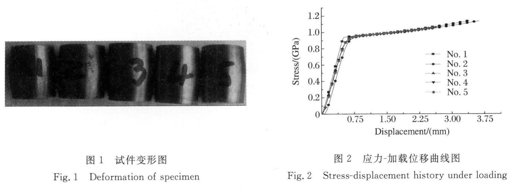
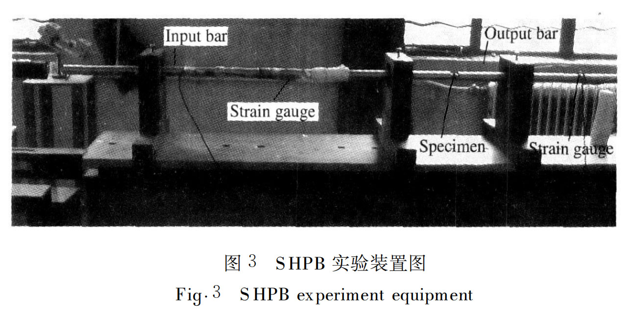
The MTS material testing machine was used to carry out quasi-static compression on the non-annealed cylindrical Ta-10W specimen with a diameter of 10mm and an axial length of 15mm at a loading speed of 1mm/min. The deformation of the specimen after compression is shown in Figure 1. As can be seen from Figure 1, during the quasi-static compression process, the specimen deforms in a drum shape, and the specimen becomes thicker as the load increases. The maximum load loaded in this experiment is about 9t. This load causes the specimen to undergo obvious plastic deformation, but it has not reached the load limit of the specimen destruction. There is no obvious crack on the surface of the specimen, indicating that the specimen material has good toughness. The relationship curve between the specimen stress and the downward displacement of the loading head calculated by the experimental test is shown in Figure 2. From the figure, it can be seen that the non-annealed Ta-10W alloy has a higher strength, and its quasi-static compression yield strength is about 930MPa.
3 Dynamic compression test method
3.1 SHPB experimental principle
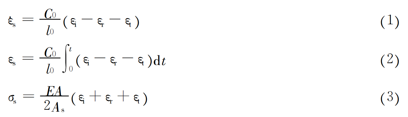
The Ta-10W dynamic compression experiment is completed on a split Hopkinson pressure bar (Split Hopkinson Pressure Bar, SHPB) experimental system with a diameter of 25mm. The loading device is shown in Figure 3, where the bullet length is 300mm, the length of the input rod and the output rod are both 1000mm, and the strain gauge is pasted to the middle of the input rod and the output rod. The principle of the S HPB experimental device is shown in Figure 4 [5]. During the experiment, the bullet hits the input rod at a certain speed, generating an incident pulse εi in the input rod. When the incident pulse propagates to the contact interface between the input rod and the specimen, part of the pulse is reflected in the input rod to form a reflected pulse εr, and the other part of the pulse is transmitted into the specimen. This part of the pulse is reflected at the contact interface between the specimen and the output rod, and the other part will form a transmitted pulse εt in the output rod. These pulse signals are measured by strain gauges attached to the input rod and the output rod respectively. The specimen deforms under the action of the stress pulse. The signals collected from the input rod and the output rod, combined with the one-dimensional stress assumption and the uniform assumption, can determine the strain rate εs(t), strain εs(t) and stress σs(t) curves of the specimen material under the action of the stress wave.
 3.2 Experimental data processing method
According to the one-dimensional wave propagation theory, the sum of the incident wave and the reflected wave signal is equal to the transmitted wave signal. Therefore, any two wave signals or three wave signals can be selected for processing to obtain the stress, strain and strain rate curves of the specimen. From the literature [12], it can be seen that the three-wave processing method based on the calculation of specimen stress and strain under absolute time has good credibility and can avoid human factors in the data processing process to the greatest extent. The traditional two-wave method is not the preferred method, but for data with only two wave signals (output rod strain gauge is broken or reflected wave signal is abnormal), the two-wave method can be used to analyze and obtain the dynamic mechanical properties of the specimen. The three-wave method is to comprehensively analyze the incident wave, reflected wave and transmitted wave signals collected in the experiment to calculate the strain rate, strain and stress curve of the specimen material. The calculation formula is (1) to (3).
Where: C0 is the elastic wave velocity of the compression rod; l0 is the initial length of the specimen; E is the elastic modulus of the compression rod; A is the cross-sectional area of the compression rod; As is the cross-sectional area of the specimen. The two-wave method is a simplification of the three-wave method based on the stress balance formula (4) at both ends of the specimen. The two wave signals collected from the three waves are used for analysis to obtain the dynamic mechanical properties of the specimen material. Here, the dynamic stress and strain of the material are calculated by taking the reflected wave and transmitted wave signals as examples. The specific processing formulas are (5) to (7).
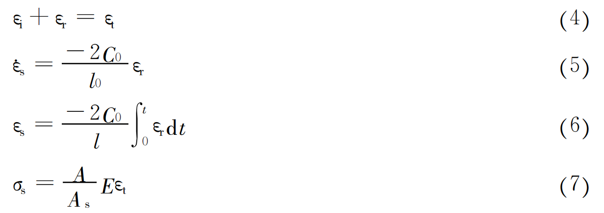
The parameters in (5) to (7) are consistent with those in (1) to (3). Further analysis of the experimental data according to the above formula can obtain the dynamic compressive stress-strain curve of the specimen and the material parameters required in the numerical simulation.
4 Dynamic compression test
4.1 Typical curves of experimental test
In the experiment, dynamic compression tests were carried out on Ta-10W specimens at different bullet speeds. The typical original waveform recorded in the experiment is shown in Figure 5, which is the test result when the bullet speed is 16∙27m/s. In the figure, the horizontal axis is time, the vertical axis is voltage signal, and the relationship between the voltage value and the strain size on the guide rod is that the strain value corresponding to each 1V voltage value is 0∙01.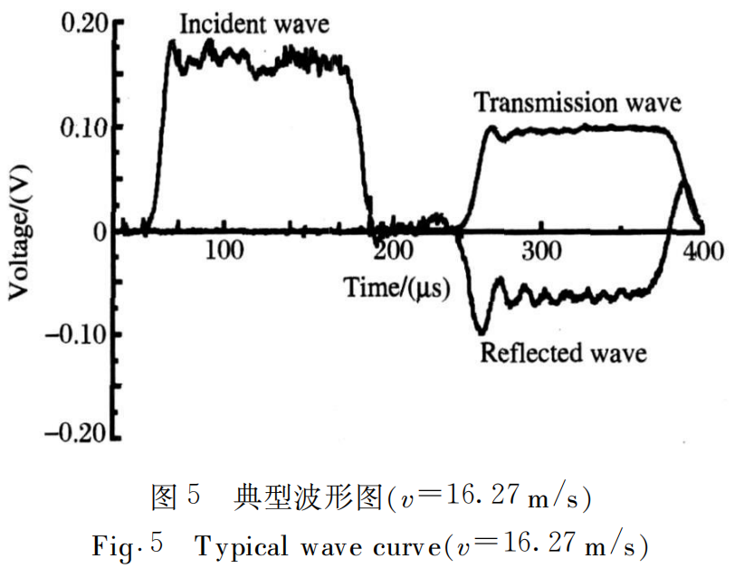
4.2 Dynamic compression test results
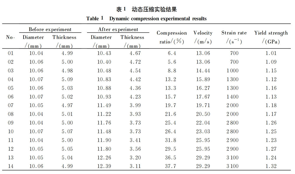
Dynamic compression tests were carried out on 14 Ta-10W specimens with a diameter of 10mm and a thickness of 5mm. The bullet speed in the experiment was 13-30m/s, and the strain rate experienced by the specimens was 700-3100s-15 strain rates. The relevant experimental conditions and experimental test analysis results are shown in Table 1. During the entire experiment, the specimens were compressed and deformed along the axial direction, and no visible cracks were generated on the surface of the specimens. As can be seen from Table 1, when the projectile velocity is 13∙06m/s, the axial compression deformation of the specimen is about 6%; as the projectile velocity increases, the compression of the specimen increases. When the projectile velocity is 29∙29m/s, the compression deformation of the specimen reaches 37%. Since the specimens are not damaged, the dynamic failure strain of the specimen is greater than 0∙37.
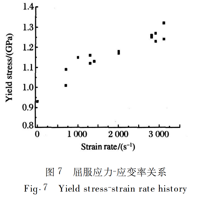
In this experiment, the incident, reflected and transmitted wave collected complete experimental data and analyzed according to the three-wave method of formula (1) to (3). The data collected only two valid waveforms were processed according to the two-wave method of formula (5) to (7) to obtain the dynamic stress-strain relationship of the Ta-10W alloy. The dynamic stress-strain curves of the specimen material at different strain rates obtained by analysis and processing are shown in Figure 6. As can be seen from Figure 6, the shapes of the dynamic stress-strain curves obtained at different strain rates are basically the same, and the plastic flow stress value obtained by the material at a high strain rate is slightly higher. Since the strain corresponding to the dynamic stress-strain curve in Figure 6 in the plastic stage includes elastic strain and plastic strain, and the compression of the specimen in Table 1 is characterized by the percentage of plastic deformation, the strain corresponding to the dynamic stress-strain curve of the specimen at different strain rates in the unloading stage is slightly greater than the percentage of compression deformation in Table 1. The deformation of the material at a low strain rate is small, that is, the corresponding strain when entering the unloading stage is small. Figure 7 is a trend diagram of the yield stress of the specimen with strain rate in quasi-static and dynamic experiments. It can be seen from the figure that the dynamic yield stress (>1GPa) of the non-annealed Ta-10W alloy is larger than the static yield strength (930MPa). Although the dynamic yield stress obtained by the experiment at the same strain rate has a certain dispersion, it is not difficult to see that with the increase of the strain rate, its dynamic yield stress shows an upward trend. Therefore, in the experimental strain rate range of 700 to 3100s-1, the yield strength of the material is rate sensitive and increases slightly with the increase of the strain rate.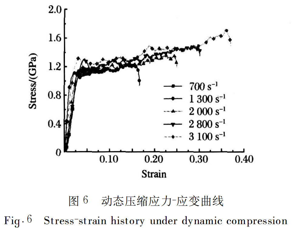
5 Conclusion
Using MTS material testing machine and S HPB experimental device, quasi-static and dynamic compression tests were carried out on the non-annealed Ta-10W alloy. The static compression yield strength of the material and the dynamic compression stress-strain curve in the strain rate range of 700-3100s-1 were given, and the yield strength of the material at different strain rates was obtained. The following conclusions can be drawn from the analysis of the experimental results:
(1) The non-annealed Ta-10W alloy has high static and dynamic compression yield strengths. The static yield strength is about 930MPa, and the dynamic flow stress is above 1GPa. Its dynamic compression strength is greater than the static strength.
(2) In the dynamic compression test with a strain rate of 700-3100s-1, the dynamic yield strength of the material increases from 1∙0GPa to 1∙3GPa. The yield strength increases with the increase of strain rate, which is rate-dependent.
(3) Within the experimental strain rate and stress range involved in this work, the Ta-10W specimen underwent a large deformation, and no visible cracks appeared on the surface. The specimen material has good toughness, and its dynamic failure strain is greater than 0∙37.
Paper citation information
Journal of High Pressure Physics
Volume 24 Issue 1
February 2010
Tantalum-tungsten alloy is a high-density material with high melting point, high tensile strength, good dynamic ductility and corrosion resistance. It is used in chemical corrosion protection, machinery, aerospace and military fields.
The spherical Ta-10W alloy powder produced by Stardust Technology is made by radio frequency plasma spheroidization process. It has the characteristics of high purity and low oxygen, high sphericity, smooth surface, no satellite, uniform particle size distribution, excellent flowability, high bulk density and tap density. It is suitable for laser/electron beam additive manufacturing, hot isostatic pressing, laser cladding, hot/cold spraying and other processes.http://en.stardusttech.cn/products_det/259.html

To learn more about Ta-10W powder characteristics and printing performance, please contact Vicky at 13318326185

News
Stardust Technology (Guangdong) Co., Ltd.

101, Building 1, Liandong Youzhi Zone, Senshuji Road, Nansha Community, Danzao Town, Nanhai District, Foshan City,Guangdong Pro.,China
Tel:13318326187
13378621675
QR code