 Co., Ltd.")
Research on the Application of Metal Additive Manufacturing Technology in the Production of Complex Mechanical Parts
Release time:
2025-08-19
0 Introduction
With the rapid development of the manufacturing industry, product structures have become increasingly complex, and the structural complexity of mechanical components and the requirements for their processing precision have continued to rise [1]. Traditional mechanical processing methods, such as turning, milling, and drilling, struggle to meet the production demands of complex parts with small batch sizes, irregular shapes, and internal cavity structures. The emergence of metal additive manufacturing technology has brought new breakthroughs in the production of complex mechanical parts. This technology enables the direct production of complex, customized metal parts through layer-by-layer material deposition, eliminating the need for complex fixtures and molds, thereby significantly reducing product development cycles and production costs. In recent years, metal additive manufacturing technology has seen rapid development and has been widely applied in fields such as aerospace, automotive, and mold manufacturing. Applying this technology to the manufacturing of complex mechanical parts is of great significance for improving product performance, shortening delivery cycles, and reducing manufacturing costs. This paper will focus on the application of metal additive manufacturing technology in the manufacturing of complex mechanical parts, analyzing its principles, key processes, and application workflows, and exploring its feasibility through experimental verification, with the aim of providing new solutions for the efficient manufacturing of complex mechanical parts.
1 Metal Additive Manufacturing Technology
Metal additive manufacturing is an emerging technology that directly manufactures components based on three-dimensional models through the layered deposition of materials. Depending on the forming method and heat source used, metal additive manufacturing processes can be categorized into laser selective melting (SLM), electron beam selective melting (EBM), laser metal deposition (LMD), and others [2]. Taking the SLM process as an example, its principle involves using a high-energy-density laser beam as the heat source. By controlling the laser scanning path, the metal powder is selectively melted to form a liquid melt pool on the substrate, which then rapidly cools and solidifies to form a solid layer. By repeating the above steps, the material is melted, solidified, and bonded layer by layer to form a three-dimensional solid. During the SLM forming process, process parameters such as laser energy density, scanning speed, powder layer thickness, and substrate preheating temperature significantly affect the forming quality and mechanical properties of the part. Appropriate process parameters can suppress residual stress, cracks, and porosity defects during the forming process, resulting in high-quality components with excellent mechanical properties and dense microstructure. Additionally, other metal additive manufacturing processes such as electron beam selective melting and laser metal deposition share similar principles with SLM. They achieve rapid part formation by employing different energy input methods and powder feeding mechanisms. The fundamental process involves using a high-energy-density heat source to selectively melt metal raw materials, enabling layer-by-layer manufacturing from point to line, line to surface, and surface to volume [3]. Metal additive manufacturing technology is not limited by the complexity of part structures, enabling the integrated manufacturing of complex internal cavity structures and non-standard structures. It is a key technology driving the transformation of complex part manufacturing processes.
2 Technical Challenges in Manufacturing Complex Mechanical Parts
The manufacturing of complex mechanical parts faces numerous technical challenges and difficulties. First, as mechanical products evolve toward lightweight, compact, and integrated designs, their structural complexity continues to increase, with features such as thin walls, long slender shapes, irregular geometries, and internal cavities becoming increasingly common, posing significant challenges for part design and processing. Second, complex mechanical parts often play a critical role in transmitting motion and bearing loads, thus requiring high precision and performance. Take aircraft engine blades as an example: their wall thickness can be as thin as 0.5 mm, with contour accuracy requirements below 0.05 mm, and they must maintain stability under extreme conditions such as high temperatures and pressures. Furthermore, complex mechanical parts widely utilize difficult-to-machine high-strength, high-toughness materials such as titanium alloys and high-temperature alloys, which have excellent physical and mechanical properties but poor machinability, rendering conventional machining methods inapplicable or extremely inefficient [4]. Additionally, diverse varieties, small batches, and customization have become the primary production model for complex mechanical parts. How to shorten production cycles and control manufacturing costs while ensuring machining quality has become an urgent issue to address. Finally, traditional mechanical processing has a long process route with many steps, resulting in lengthy production times and insufficient production capacity, making it difficult to meet the market demand for rapid delivery. In summary, the manufacturing of complex mechanical parts generally faces challenges such as difficult machining, low efficiency, high costs, and long lead times, necessitating new processes and methods to overcome the limitations of traditional manufacturing technologies.
3 Application Process and Key Points of Metal Additive Manufacturing Technology
3.1 Three-Dimensional Design of Mechanical Part Models
Three-dimensional design of mechanical parts is the primary step and core foundation of the metal additive manufacturing process. Designers must comprehensively consider factors such as the structural characteristics, functional requirements, material properties, and forming processes of the parts, and use computer-aided design (CAD) software to construct three-dimensional models. Additive manufacturing imposes stringent quality requirements on 3D models, which must possess complete geometric topology information and must not contain errors such as missing faces or self-intersections. Additionally, structural design and optimization are required, such as replacing solid structures with truss structures to reduce weight, adding support structures at appropriate locations to prevent deformation, and reserving sufficient machining allowances for subsequent processing [5]. Furthermore, the design must fully leverage the advantages of additive manufacturing, such as integrating multiple parts into a single structure and designing complex internal cavities and irregular structures that are difficult to achieve with conventional processes. Optimization methods such as topology optimization and parametric modeling can be employed to minimize material usage and reduce printing time while ensuring functional performance.
After design completion, the model must undergo slicing to discretize it into a series of parallel two-dimensional layers, generating CNC machining code. Slicing parameter settings impact print quality; layer thickness typically ranges from 20 to 100 μm. If layer thickness is too large, surface roughness increases and contour accuracy decreases; if too small, print time extends and manufacturing costs rise. Therefore, it is necessary to comprehensively consider precision and efficiency to select the optimal slicing parameters. In summary, the three-dimensional design of mechanical parts is a critical step in metal additive manufacturing, and the quality and structural optimization of the model directly determine the performance and efficiency of the manufactured part.
3.2 Process parameter settings for metal additive manufacturing
Process parameter settings are critical to achieving high-quality components in metal additive manufacturing. Key parameters include laser power, scanning speed, spot diameter, powder layer thickness, and scanning spacing. Different combinations of these parameters affect part dimensional accuracy, surface quality, and mechanical properties. First, laser power and scanning speed determine the energy input per unit area. Excessively high energy density can cause material evaporation and burn damage, while insufficient energy density can result in incomplete melting and bonding defects. Therefore, it is necessary to select an optimal power-speed combination based on the material's thermophysical properties. For example, in SLM forming of 316L stainless steel, the laser power is typically 200–400 W, and the scanning speed is 800–1500 mm/s. Second, the spot diameter and scan spacing jointly determine the size and overlap rate of the heat-affected zone, affecting the stability of the melt pool and the surface quality of the formed part. The spot diameter is typically 50–200 μm, and the scan spacing is 50–150 μm. The ratio between the two must be controlled between 0.5 and 0.8 to achieve a uniform and continuous melting trajectory. Furthermore, the powder layer thickness is closely related to the powder particle size. Selecting an appropriate layer thickness can improve forming efficiency while ensuring complete melting. The powder layer thickness is generally 2–3 times the average powder particle size. Excessively thick powder layers can cause powder accumulation, hindering the metallurgical bonding between the melt pool and the substrate. In addition to the above parameters, preheating temperature, argon gas flow rate, and scanning strategies also affect part forming quality and residual stress. Therefore, process parameter optimization is a complex, multi-objective, and strongly coupled process that requires extensive experimentation, combined with numerical simulation and machine learning techniques, to establish a mapping model between process parameters and performance, thereby achieving precise control and intelligent optimization of the forming process.
3.3 Printing of complex parts
After completing the 3D model design and process parameter settings, the printing process for complex parts can be formally executed. First, the part model is imported into the control software of the additive manufacturing equipment. A suitable substrate is selected based on the part dimensions, and a layer of binder identical to the metal powder material is applied to the substrate surface to enhance the adhesion between the first layer of powder and the substrate. Then, the equipment spreads a layer of metal powder uniformly using a scraper or roller according to the pre-set powder layer thickness, and uses a high-energy beam scanning system to selectively melt the powder. Taking laser selective melting as an example, the laser beam scans the powder bed surface along a pre-planned scanning path at a certain speed and power density, causing the powder to absorb energy, melt, solidify, and metallurgically bond, forming a solidified layer of a specific shape. To prevent oxidation of the melt pool, the forming process must be conducted in a high-purity inert atmosphere (such as argon) with real-time monitoring and adjustment of oxygen content. After one powder layer is completed, the substrate descends by one powder layer thickness, and the powder spreading and scanning process is repeated until the entire part is manufactured.
During the printing process, it is necessary to monitor key parameters such as laser power, scanning speed, and substrate temperature in real time to ensure they remain within the specified range. If any abnormalities are detected, the machine must be shut down immediately for inspection to prevent defects from worsening. For parts with complex structures and overhang angles exceeding 45°, deformation and collapse issues may occur during printing. Therefore, it is essential to design reasonable support structures and incorporate heat dissipation channels to mitigate temperature gradients. Additionally, for large-sized irregular parts, a printing strategy involving regional, hierarchical, and directional segmentation can be adopted to reduce residual stress and improve forming efficiency. After printing is complete, the part should be allowed to cool to room temperature before separating it from the substrate and removing any powder adhering to the surface. At this point, the printing execution phase for complex parts is complete, and the part will proceed to the post-processing stage.
3.4 Post-processing of formed parts
Although metal additive manufacturing can directly produce complex parts with near-net shapes, the surface quality and precision of formed parts often fail to meet usage requirements, necessitating necessary post-processing. First, the part surface typically retains a large amount of powder particles and fusion spatter, resulting in a surface roughness Ra of 20–30 μm, which requires surface cleaning via methods such as shot blasting or sandpaper grinding. Second, support structures form at the interface between the formed part and the substrate, which can interfere with assembly and use. These supports must be removed using methods such as band saw cutting or wire cutting. Additionally, the rapid solidification of materials during additive manufacturing can result in significant residual tensile stresses within the part, along with pronounced anisotropy in microstructural properties. Therefore, heat treatment processes are required to eliminate stresses, adjust microstructures, and enhance the uniformity of mechanical properties. Additionally, for parts with complex structures and narrow internal cavities, conventional machining methods struggle to access the interior for precision finishing. Additive manufacturing combined with CNC technology offers a new approach. Using ultrasonic vibration-assisted electrolytic machining, a mirror-like surface finish with a surface roughness Ra of 0.4 μm can be achieved on complex parts; Alternating between CNC milling and additive manufacturing enables “integrated” precision manufacturing of parts, with machining allowances controlled within 0.1 mm. Finally, non-destructive testing of parts after forming is also critical. Methods such as X-ray and ultrasonic testing can be used to detect internal defects like cracks and incomplete fusion, ensuring that part performance meets design requirements. It should be noted that while post-processing can improve part performance, it also increases manufacturing costs and extends production cycles. Therefore, post-processing strategies must comprehensively consider technical and economic factors, minimizing post-processing steps to enhance part quality from the source. This requires continuous optimization of design, materials, processes, and equipment.
4 Experimental Validation
4.1 Experimental Design
To validate the application effectiveness of metal additive manufacturing technology in the production of complex mechanical parts, this study selected a certain type of aircraft engine turbine blade as the experimental subject. The blade features a complex twisted surface, internal cooling channels, and a thin-walled structure, with the thinnest wall thickness of only 0.8 mm. A comparative testing method was employed, with the same specifications of turbine blades manufactured using metal additive manufacturing technology (experimental group) and traditional five-axis CNC machining technology (control group). The testing was conducted at the engineering center of a certain aerospace manufacturing company and lasted for three months. The experimental group used a German EOS M290 selective laser melting device with a laser power of 400W, a scanning speed of 1200mm/s, a spot diameter of 100μm, and a layer thickness of 30μm. The experimental material selected was GH4169 high-temperature alloy powder with a particle size distribution of 15–45μm. The control group used a DMU80 five-axis machining center from DMG to process GH4169 forgings as raw materials. The experimental group's manufacturing process was as follows: 3D modeling (UG software) → model slicing (Magics software) → process parameter optimization → SLM forming → heat treatment (950°C/4h vacuum annealing) → support removal → finishing. The manufacturing process for the control group was: blank forging → rough machining → semi-finishing → finishing → polishing → inspection.
Evaluation criteria included: (1) dimensional accuracy, measured using a coordinate measuring machine with a tolerance of ≤0.05 mm; (2) surface quality, measured using a roughness tester with a tolerance of Ra ≤1.6 μm; (3) Mechanical properties, tested via tensile testing for tensile strength, with a requirement of no less than 1000 MPa; (4) Production efficiency, recorded as the complete manufacturing cycle from raw data to finished product. Experimental data was analyzed using SPSS software to assess the advantages and disadvantages of the two manufacturing methods. This experiment systematically validated the process feasibility, quality stability, and economic benefits of metal additive manufacturing technology in the production of complex mechanical parts.
4.2 Experimental Results
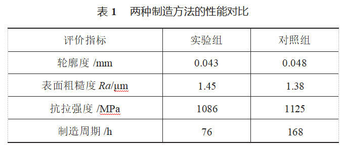
Through systematic testing and analysis of turbine blades from the experimental group and control group, comparative data for the two manufacturing methods were obtained. As shown in Table 1, in terms of dimensional accuracy, the blade contour accuracy achieved by metal additive manufacturing technology was 0.043 mm, slightly better than the 0.048 mm achieved by traditional five-axis machining. This is primarily due to the layer-by-layer deposition characteristics of the SLM process and the optimized scanning strategy. Surface quality test results indicate that the surface roughness Ra of blades produced using additive manufacturing technology, after post-processing, reached 1.45 μm, which is comparable to the 1.38 μm achieved by traditional machining methods, both meeting design requirements. Mechanical property testing shows that the tensile strength of blades produced using additive manufacturing technology is 1086 MPa, approximately 3.5% lower than the 1125 MPa achieved by traditional processes. This may be attributed to micro-pores formed during the SLM process. In terms of production efficiency, metal additive manufacturing technology demonstrates a significant advantage, with the entire process from data modeling to finished product completion taking only 76 hours, compared to 168 hours for traditional processes, representing a 54.8% efficiency improvement. This efficiency gain is primarily achieved by eliminating processes such as blank preparation and rough machining, enabling the integrated forming of parts.
Experimental data indicate that metal additive manufacturing technology enhances manufacturing efficiency for complex mechanical parts while ensuring part performance, making it particularly suitable for small-batch, customized production of highly complex parts. Although there are minor performance gaps compared to traditional processes in certain metrics, its overall performance already meets engineering application requirements.
5 Conclusion
Metal additive manufacturing technology offers a new solution for the production of complex mechanical parts. Through systematic research into its process principles, application workflows, and experimental validation, this technology can enhance manufacturing efficiency and shorten production cycles while ensuring part performance. Experimental results indicate that turbine blades produced using this technology meet engineering application requirements in terms of contour accuracy, surface quality, and mechanical properties, demonstrating promising application prospects. However, there is still room for improvement in terms of material costs, surface quality, and mechanical properties. In the future, with the continuous development of laser technology, materials science, and intelligent control, the process stability and part performance of metal additive manufacturing will further improve. Additionally, by establishing standardized process specifications and quality control systems, this technology is expected to achieve broader engineering applications in fields such as aerospace, automotive, and new energy.
References: Issue 14, 2025 Liu Dewei: Research on the Application of Metal Additive Manufacturing Technology in the Manufacturing of Complex Mechanical Parts Mechanical Manufacturing and Intelligence
Stardust Technology (Guangdong) Co., Ltd. specializes in the research, development, and production of high-end spherical metal powder materials. Leveraging radiofrequency plasma spheroidization technology, the company offers 3D printing services, providing high-purity, high-spherical-degree tantalum, tungsten, molybdenum, and other refractory metal powders suitable for laser/electron beam additive manufacturing, hot isostatic pressing, laser cladding, and other processes. The company has made significant strides in the medical field, with 3D-printed tantalum metal orthopedic implants (such as intervertebral fusion devices and hip joint prostheses) successfully applied in nearly 1,000 clinical surgeries. It has also participated in the formulation of multiple national and industry standards. Additionally, Stardust Technology offers customized 3D printing solutions for high-end sectors such as aerospace and defense. For more details, please feel free to contact our professional staff: Cathie Zheng at +86 13318326187.

News
Stardust Technology (Guangdong) Co., Ltd.

101, Building 1, Liandong Youzhi Zone, Senshuji Road, Nansha Community, Danzao Town, Nanhai District, Foshan City,Guangdong Pro.,China
Tel:13318326187
13378621675
QR code